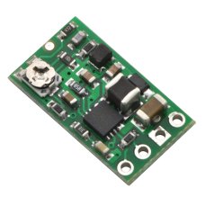
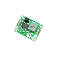
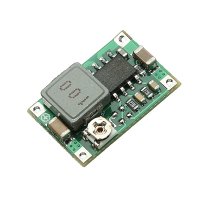
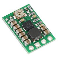
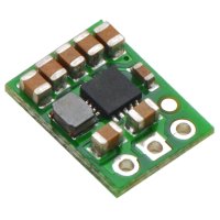
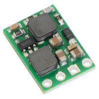
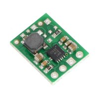
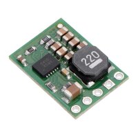
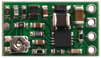
This switching regulator uses the SEPIC topology to provide a regulated output voltage that can be higher than, the same as, or lower than the input voltage, making it great for applications with widely-varying power supplies and for battery-operated applications where the battery transitions from being above the output to below the output as it discharges. The small (0.4″×0.7″) module can support input voltages from 1.5 V to 12 V, has an adjustable output from 2 V to 12 V, and can supply over 300 mA in typical applications.
The Pololu step-up/step-down voltage regulator S8V3A is a switching regulator (also called a switched-mode power supply (SMPS) or DC-to-DC converter) with a single-ended primary-inductor converter (SEPIC) topology. It takes an input voltage from 1.5 V to 12 V and increases or decreases the voltage to a user-adjustable output voltage between 2 V and 12 V. The input voltage can be higher than, lower than, or equal to the set output voltage, and the voltage is regulated to achieve the set output voltage.
This flexibility in input voltage is especially well-suited for battery-powered applications in which the battery voltage begins above the desired output voltage and drops below the target as the battery discharges. Without the typical restriction on the battery voltage staying above the required voltage throughout its life, new battery packs and form factors can be considered. For instance, a 4-cell battery holder, which might have a 6 V output with fresh alkalines but a 4.8 V nominal voltage with NiMH cells and a 4.0 V output with partially discharged cells, can now be used for a 5 V circuit. A single lithium-polymer cell can run a 3.3 V device through its whole discharge cycle. In another typical scenario, a disposable 9V battery powering a 5 V circuit can get completely discharged to 1.5 V instead of cutting out at 6 V, as with typical linear or step-down regulators.
The S8V3A regulator has a shutdown feature that can also be used as an under-voltage protection mechanism for batteries that respond poorly to being over-discharged. The shutdown threshold can be set with one external resistor; please see the Shutdown section below for details.
 |
This regulator can deliver 300 mA continuous in typical applications where the output voltage is not too far from the input voltage. The regulator has under-voltage protection, and thermal shutdown prevents damage from overheating; the board does not have reverse-voltage protection. For applications where the output is significantly different from the input, a regulator optimized for boosting (stepping up) or bucking (stepping down) is more efficient, but for small applications where efficiency is not a top priority, this board can be a convenient, general-purpose regulator to give your system a wide range of supported input voltages.
For a similar regulator with higher efficiency, consider our step-up/step-down voltage regulator S7V8A.
Features
- output voltage that can be higher than, the same as, or lower than the input voltage
- recommended input voltage: 1.5 V to 12 V
- output voltage adjustable between 2 V and 12 V
- typical continuous output current: 300 mA (Actual continuous output current depends on input voltage. See Typical Efficiency and Output Current section below for details)
- 1.5 MHz switching frequency
- integrated over-temperature protection
- small size: 0.40" x 0.70" x 0.15" (10 x 18 x 4 mm)
 |
|
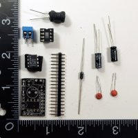
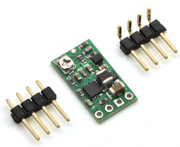
Pololu step-up/step-down voltage regulator S8V3A with included hardware. |
|---|
Using the Regulator
During normal operation, this product can get hot enough to burn you. Take care when handling this product or other components connected to it.
Connections
The step-up/step-down regulator has 4 connections: input voltage (VIN), ground (GND), output voltage (VOUT), and shutdown (SHDN).
The input voltage, VIN, should be between 2 V and 12 V. GND should be at 0 V. Inputs below 1.5V can shut down the voltage regulator; inputs above 16V can destroy the regulator. Therefore, you should ensure that noise on your input does not exceed the 16 V maximum, and you should be wary of destructive LC spikes (see below for more information).
The output voltage, VOUT, is determined by the trimmer potentiometer position. See the Setting the Output Voltage section below for details.
Shutdown
If the voltage on the SHDN pin drops below 1.1 V, the regulator will turn off. The SHDN pin is pulled up to VIN by a 130 kΩ resistor; by adding a resistor between SHDN and GND, you can set the shutdown voltage by making the SHDN pin cross 1.1 V when your input voltage crosses your desired threshold. If we call that threshold VOFF, the equation for the resistor to connect from SHDN to GND is:
 |
For example, if you want to set VOFF to 4 V, so that your battery does not discharge below 4 V, you should connect a 40kΩ resistor between SHDN and GND. The shutdown circuitry has a 0.6 V hysteresis; after the input voltage falls below VOFF the regulator will not turn back on until the voltage rises above VOFF + 0.6 V.
Setting the Output Voltage
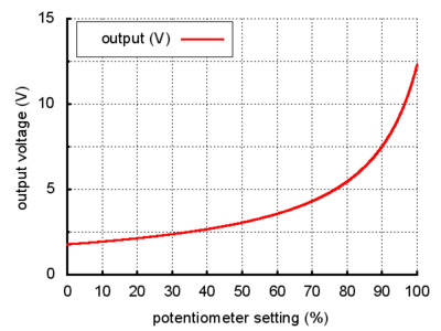
The output voltage can be measured using a multimeter. Turning the potentiometer clockwise increases the output voltage. The output voltage can be affected by a screwdriver touching the potentiometer, so the output measurement should be done with nothing touching the potentiometer.
 |
|
Output voltage settings for the step-up/step-down voltage regulator S8V3A. |
|---|
Typical Efficiency and Output Current
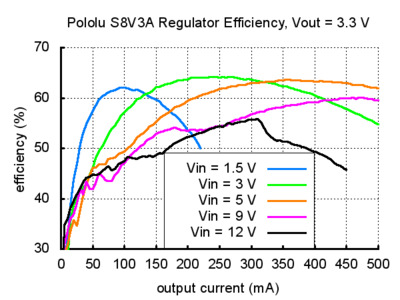
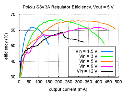
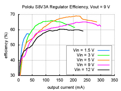
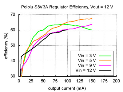
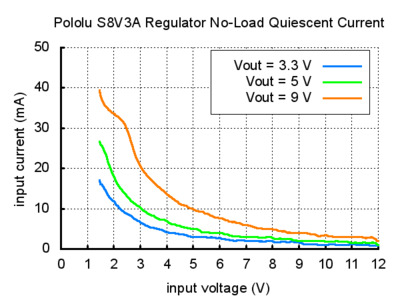
The efficiency of a voltage regulator, defined as (Power out)/(Power in), is an important measure of its performance, especially when battery life or heat are concerns. As shown in the graphs below, this switching regulator typically has an efficiency of 55% to 65%. The maximum achievable output current of the board depends on many factors, including the ambient temperature, air flow, heat sinking, and the input and output voltage. See the graphs below for more details on the typical efficiency and output currents for this voltage regulator.
LC Voltage Spikes
When connecting voltage to electronic circuits, the initial rush of current can cause voltage spikes that are much higher than the input voltage. If these spikes exceed the regulator’s absolute maximum voltage (16 V), the regulator can be destroyed. In our tests with typical power leads (~30" test clips), input voltages above 10 V caused spikes over 16 V. If you are connecting more than 10 V or your power leads or supply has high inductance, we recommend soldering a 33μF or larger electrolytic capacitor close to the regulator between VIN and GND. The capacitor should be rated for at least 25 V.
More information about LC spikes can be found in our application note, Understanding Destructive LC Voltage Spikes.
Dimensions
| Size: | 0.40" x 0.70" x 0.15"1 |
|---|---|
| Weight: | 0.7 g1 |
General specifications
| Minimum operating voltage: | 1.5 V |
|---|---|
| Maximum operating voltage: | 16 V |
| Maximum output current: | 300 mA2 |
| Minimum output voltage: | 2 V |
| Maximum output voltage: | 12 V |
| Reverse voltage protection?: | N |
Identifying markings
| PCB dev codes: | reg06a |
|---|---|
| Other PCB markings: | 0J2411 |
Notes:
- 1
- Without included hardware.
- 2
- Typical maximum that can be delivered continuously without overheating. Actual maximum output current depends on input and output voltages.
| Electrical Specifications | |
| Output Voltage | Minimum output voltage:2 V, Maximum output voltage:12 V |
| Output Current | 300mA |
| Minimum Operating Voltage | 1.5V |
| Maximum Operating Voltage | 16V |
| Physical Attributes | |
| Weight | 0.7g |
| Dimensions | 0.40" x 0.70" x 0.15" |
| Additional Information | |
| Warranty | |
Pololu 2120 Adjustable Step-Up/Step-Down Voltage Regulator S8V3A
- Brand: Pololu
- Product Code: Pololu-Step-Up-Down-S8V3A
- Reward Points: 8
- Availability: In Stock
- रo 778.00
-
रo 747.00
- Price in reward points: 778
Related Products
LM2596 DC to DC Step Down Adjustable Power Supply Module
Features:Adjustment method: first correct input power (between 4.5-50V) then multimeter to monitor t..
रo 90.00 रo 165.00
AMS1117 - 3.3V Power Supply Module
Key Features Input: DC 4.5V--7V Output: 3.3V, 800mA (load current can not exceed 800ma) Dual..
रo 30.00 रo 40.00
AMS1117 - 5V Power Supply Module
Key Features 1.Input: DC 6V - 12V 2.Output: 5.0V (+-0.05v error), 800mA (load current can no..
रo 102.00
Boost Kit
The Boost Shield Kit allows you to use supply voltages under 5v with the Digispark development board..
रo 220.00 रo 1,580.00
LM2596 DC to DC Step Down Module + LED Voltmeter
LM2596 Power Step-down Module DC 4.0~40 to 1.3-37V Adjustable + Voltmeter LED Display Feat..
रo 250.00 रo 485.00
Heat Sink - Aluminum with Glue (11mm)
These are high quality heat sink with heat conduction glue that can be used for dissipating the heat..
रo 13.00
XM1584 Ultra-Small Size DC-DC Step-Down Power Supply Module
XM1584 Ultra-small size DC-DC step-down 3A adjustable power supply module. Features and Specific..
रo 81.00
Amplifier Board TDA7498 100W+100W Class D
TDA7498 is 100W +100 W amplifier, using support monolithic integrated analog, logic and high pressur..
रo 1,678.00
DSN Mini 360 DC Adjustable Step Down Power Supply Module
Mini DC Adjustable Power Supply Buck Module Step Down Module Specifications: Modul..
रo 115.00 रo 130.00
Voltage Converter TPS5401DGQT 3.5V-42Vin,0.5A Step Down SWIFT
Voltage Converter TPS5401DGQT 3.5V-42Vin,0.5A Step Down SWIFT Specifications: Topology :..
रo 150.00
AC-DC Power Supply Buck Converter Step Down Module 5V 700mA
This power supply has the temperature protection, over current protection and short circuit protecti..
रo 140.00 रo 230.00
DC-DC Adjustable Step-up Power Converter Board 0.9V - 5V
DC-DC Adjustable Step-up Power Converter Board 0.9V - 5V Features Input volta..
रo 77.00
Regulator Step-up/ Step-Down - 5V
High precision, special design for micro FPV, easy soldering like a distribution board. No moto..
रo 1,216.00 रo 1,267.00
Pololu 2574/2575/2576/2577/2572/2573 5V/ 6V/ 9V/ 12V/ 4-12V/ 9-30V Step-Up/Step-Down Voltage Regulator S18V20F5/ 6/ 9/ 12/ ALV/ AHV
This powerful S18V20F5 S18V20F6 S18V20F9 S18V20F12 step-up/step-down regulator efficiently produces ..
रo 2,092.00 रo 2,179.00
Pololu 2118 Adjustable Step-Up/Step-Down Voltage Regulator S7V8A
The S7V8A switching step-up/step-down regulator efficiently produces an adjustable output between 2...
रo 602.00 रo 628.00
Pololu 2122 3.3V Step-Up/Step-Down Voltage Regulator S7V8F3
The S7V8F3 switching step-up/step-down regulator efficiently produces a fixed 3.3 V output from inpu..
रo 602.00 रo 628.00
Pololu 2123 5V Step-Up/Step-Down Voltage Regulator S7V8F5
The S7V8F5 switching step-up/step-down regulator efficiently produces a fixed 5 V output from input ..
रo 602.00 रo 628.00
Pololu 2119 5V Step-Up/Step-Down Voltage Regulator S7V7F5
The S7V7F5 switching step-up/step-down regulator efficiently produces 5 V from input voltages betwee..
रo 527.00 रo 549.00
Pololu 2095 / 2096 / 2121 DC-DC Step Up Power Converter Booster - MT3608
This switching regulator uses the SEPIC topology to produce 5 V/9 V/12 V from input voltages between..
रo 844.00 रo 879.00
Pololu 2561/2562 3.3/ 5V Step-Up Voltage Regulator U1V11F3/ U1V11F5
This compact (0.45″×0.6″) U1V11F3/ U1V11F5 switching step-up (or boost) voltage regulator efficientl..
रo 527.00 रo 549.00
Pololu 2830 / 2831 / 2832 / 2833 / 2834 1A Step-Down Voltage Regulator D24V10F3/ 5/ 6/ 9/ 12
The compact (0.5″ × 0.7″) D24V10F3/ 5/ 6/ 9/ 12 synchronous buck voltage regulator takes an input vo..
रo 754.00 रo 786.00
LM317 DC-DC Converter Buck Step Down Voltage Regulator
LM317 DC-DC Converter Buck Step Down Voltage Regulator Features: 1.Output ..
रo 90.00
Tags: Pololu, Adjustable, Step-Up, Step-Down, Voltage, Regulator, S8V3A

