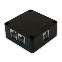
HiTechnic SuperPro Sensor for LEGO Mindstorms NXT
Introduction
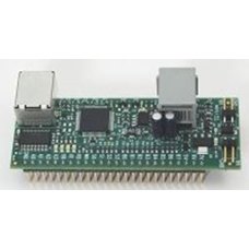
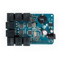
The HiTechnic SuperPro Sensor creates an easy-to-use platform for building your own sensors and safely experiment with electronic that can be directly connected to the LEGO NXT via an NXT sensor port. For applications that do not require an

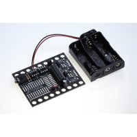
The SuperPro Prototype Board is designed to connect to a solderless breadboard allowing reuse of electronic components.
Specifications

-
3 Power Outputs
- 3.3 volts regulated at 15mA from NXT
- 5.0 volts regulated at 8mA from NXT
- 9v volts unregulated at 8mA from NXT
- 3.3 volts, 5.0 volts and 9 volts from external battery connection if applied
-
4 Analog Inputs (A0 – A3)
-
0 -
3.3 volt range - 10 bit A/D conversion
-
0 -
-
8 Digital I/O (B0 – B7)
- Individually configurable as inputs or outputs, 0 or 3.3 volts
-
220 ohm output series resistor
-
2 Analog Outputs (O0, O1)
- 0 – 3.3 volts via 10 bit D/A conversion
-
7 analog modes:
- DC voltage level
- Sine wave
- Square wave
- Positive going sawtooth
- Negative going sawtooth
- Triangle wave
- PWM voltage
-
220 ohm output series resistor
-
6 Digital Strobe Outputs (S0 – S3, RD, WR)
-
- 4 can be set to logic 0 or 1 (0 or 3.3v)
- 1 pre-configured read strobe
- 1 pre-configured write strobe
-
220 ohm output series resistor
-
-
Onboard memory
- 12k user RAM
- 56k user program FLASH
- 1Mb external storage FLASH
-
Onboard Firmware Features
- NXT I/O data and command connection
- USB I/O
- Onboard program execution
- Multiple simultaneous user processes
-
Onboard
datalogging
Note that the digital,
I2C Interface
The SuperPro uses I2C device address of 0x10.
|
Address
|
Type
|
Field
|
|
00 – 07H
|
chars
|
Sensor version number
|
|
08 – 0FH
|
chars
|
Manufacturer
|
|
10 – 17H
|
chars
|
Sensor type
|
|
42-43H
|
byte
|
Analog input A0; upper 8 bits, lower 2 bits
|
|
44-45H
|
byte
|
Analog input A1; upper 8 bits, lower 2 bits
|
|
46-47H
|
byte
|
Analog input A2; upper 8 bits, lower 2 bits
|
|
48-49H
|
byte
|
Analog input A3; upper 8 bits, lower 2 bits
|
|
4CH
|
byte
|
Digital inputs (bits B0 – B7)
|
|
4DH
|
byte
|
Digital outputs (bits B0 – B7)
|
|
4EH
|
byte
|
Digital input/output control (bits B0 – B7)
|
|
50H
|
byte
|
Strobe output (bits S0 - S3)
|
|
51H
|
byte
|
LED control(0=none, 1=Red, 2=Blue, 3=Red and Blue)
|
|
52H
|
byte
|
Analog output O0 mode
|
|
53-54H
|
byte
|
Analog output O0 frequency;
|
|
55-56H
|
byte
|
Analog output O0 voltage; upper 8 bits, lower 2 bits
|
|
57H
|
byte
|
Analog output O1 mode
|
|
58-59H
|
byte
|
Analog output O1 frequency;
|
|
5A-5BH
|
byte
|
Analog output O1 voltage; upper 8 bits, lower 2 bits
|
The Sensor version number field returns the revision number in the format “
The Manufacturer field contains “HiTechnc”.
The Sensor type field contains “Proto ”.
The A0–A3 analog inputs contain the upper 8 bits in the first byte and the lower 2 bits in the second byte.
The Digital inputs field returns the state of the eight digital signals in bits 0–7.
The Digital outputs field sets the state of the six digital signals which have been configured as outputs.
The Digital input/output control field configures the direction of the eight digital pins B0-B7. Set the corresponding bit to 0 for input and 1 for output.
The Strong output field sets the state of the 4 general purpose strobe outputs, pins S0-S3.
The LED control field sets the state of the two on-board LEDs. Bit 0 for
The Analog mode field sets the analog mode of the analog output O0 or O1.
The Analog frequency field sets the analog frequency, 1-8191.
The Analog Voltage field sets the voltage level of the analog output O0 or O1. upper 8 bits, then lower 2 bits.
The prototyping sensor board electronics derives a stabilized 3.3v internal supply from either the NXT supplied 4.3v source or an internal 4.3v source derived from an external 9v supply. Use of a low dropout regulator will permit continued operation with supply input down to 3.6v. Operation below 3.6v input will be unreliable. The board electronics also derives a stabilized 5.0v from the supplied 9v source. The 9v may be either obtained from the NXT or an external 9v source connected between the 9v and GD connections.
Programming
Programs for the HiTechnic SuperPro Prototype Board can be developed using any of the popular NXT programming languages.
NXT-G SuperPro Sensor Programming Block
The SuperPro NXT-G programming block makes it easy to write programs that interface with the SuperPro board. The configuration panel allows selecting an action to read or write to any of the analog or digital ports.

All the parameters can also be used by using data wires to pass the data to the SuperPro.
 |
|
LabVIEW
Use LabVIEW 2009 or LabVVIEW for LEGO Mindstorms (2010) for programming the NXT to interface with the SuperPro. VIs allow reading and writing to both the analog and digital ports as well as to control the 2 onboard LEDs. Here is an example of a program to read the analog and display the result on the NXT screen:

NXC and SPC
The latest test release of BricxCC/NXC, dated 10/24/2011 or later, includes support for programming the NXT to interface with the SuperPro as well as writing programs in SPC, SuperPro C, that run right on the SuperPro board. See NXC/NBC/SPC site for more information.
RobotC
It is also possible to interface with the SuperPro using RobotC version 2.0 or higher.
Caution
The Prototype sensor and electronic components used to create circuits may be damaged by static discharge so care must be taken when handling the prototype board and components to avoid static.

HiTechnic NXT SuperPro Prototype Board
- Brand: HiTechnic
- Product Code: Hitechnic-NXT-SuperPro-Prototype
- Reward Points: 34
- Availability: In Stock
-
रo 3,400.00
- Price in reward points: 3400
Related Products
Lego Mindstorm Acceleration / Tilt Sensor for NXT / EV3
Now you can make robots that know which way is up! The Accelerometer / Tilt Sensor measures accelera..
रo 6,920.00 रo 7,550.00
Lego Mindstorms Magnetic Compass Sensor for NXT / EV3
Expand your NXT experiences with the new NXT Compass Sensor and add accurate navigation to your Mind..
रo 7,385.00 रo 7,550.00
Lego Mindstorms Infrared Seeker V2 for NXT / EV3
Play robot soccer and zero in on your infrared (IR) beacons with IRSeeker. You can use most TV remot..
रo 6,920.00 रo 6,985.00
Lego Mindstorms Color Sensor V2 for NXT / EV3
Add a spectrum of color to your models with the new and updated Color Sensor. Detect an extended ran..
रo 6,920.00 रo 7,550.00
PICAXE I2C Explorer Kit AXE216
A self-assembly kit for the PICAXE-20X2 (included) for those wishing to interface and experiment wit..
रo 1,350.00
BrickPi+ Base Kit
BrickPi is best for someone who already has LEGO MINDSTORMS sensors and motors. The BrickPi connects..
रo 17,563.00
EV3 Infrared Beacon
This has been designed for use with the EV3 Infrared Seeker Sensor. The beacon emits an infrared sig..
रo 4,425.00
EV3 Infrared Sensor
The digital EV3 Infrared Seeking Sensor detects proximity to the robot and reads signals emitted by ..
रo 4,425.00
EV3 Color Sensor
The digital EV3 Color Sensor distinguishes between eight different colors. It also serves as a light..
रo 5,175.00 रo 5,885.00
EV3 Ultrasonic Sensor
The digital EV3 Ultrasonic Sensor generates sound waves and reads their echoes to detect and measure..
रo 4,425.00
EV3 Gyro Sensor
The digital EV3 Gyro Sensor measures the robot’s rotational motion and changes in its orientation. S..
रo 4,425.00
Lego Mindstorms NXT Magnetic Sensor
The NXT Magnetic Sensor will enable you to build robots that can detect magnetic fields. The sensor ..
रo 2,865.00
Lego Mindstorms NXT IR Receiver Sensor
The NXT IRReceiver Sensor receives signals from a LEGO Power Functions IR remote control, decodes th..
रo 6,280.00
Lego Mindstorms NXT EOPD
Accurately detect objects and small changes in distance to a target with the HiTechnic EOPD. The EOP..
रo 6,920.00
Lego Mindstorms NXT Angle Sensor
Measure axle rotation position and rotation speed with the HiTechnic Angle Sensor. The Angle Sensor ..
रo 6,920.00
Lego Mindstorms NXT Barometric Sensor
The NXT Barometric Sensor can be used as part of a weather station or to monitor altitude. The senso..
रo 6,920.00
HiTechnic NXT Touch Sensor Multiplexer
HiTechnic NXT Touch Sensor Multiplexer for LEGO Mindstorms NXT Introduction The NXT Touc..
रo 3,610.00

