 |
 |


| Plug | Data Type | Possible Range | What the Values Mean |
| Port | Number | 1 - 4 | 1 = Port 1, 2 = Port 2, 3 = Port 3, 4 = Port 4 |
| Channel | Numeric | 1 - 4 | 1 = Channel l, 2 = Channel 2, 3 = Channel 3, 4 = Channel 4 |
| Direction | Logic | True/False |
True = Forwards False = Backwards |
| Power | Number | 0 - 100 | |
| Brake | Logic | True/False |
True = Brake False = Coast |
| Setting | Number | -7 - +7 | Remote speed control setting |
|
Address |
Type |
Contents |
|
00 – 07H |
chars |
Sensor version number |
|
08 – 0FH |
chars |
Manufacturer |
|
10 – 17H |
chars |
Sensor type |
|
18 – 3DH |
bytes |
Not used |
|
3E, 41H |
chars |
Reserved |
|
42H |
byte |
Motor 1A control |
|
43H |
byte |
Motor 1B control |
|
44H |
byte |
Motor 2A control |
|
45H |
byte |
Motor 2B control |
|
46H |
byte |
Motor 3A control |
|
47H |
byte |
Motor 3B control |
|
48H |
byte |
Motor 4A control |
|
49H |
byte |
Motor 4B control |
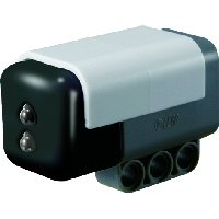
Lego Mindstorms NXT IR Receiver Sensor
- Brand: HiTechnic
- Product Code: Hitechnic-Infrared-Receiver
- Reward Points: 60
- Availability: In Stock
-
रo 6,280.00
- Price in reward points: 6280
Related Products
Lego Mindstorm Acceleration / Tilt Sensor for NXT / EV3
Now you can make robots that know which way is up! The Accelerometer / Tilt Sensor measures accelera..
रo 6,920.00 रo 7,550.00
Lego Mindstorms Magnetic Compass Sensor for NXT / EV3
Expand your NXT experiences with the new NXT Compass Sensor and add accurate navigation to your Mind..
रo 7,385.00 रo 7,550.00
Lego Mindstorms Infrared Seeker V2 for NXT / EV3
Play robot soccer and zero in on your infrared (IR) beacons with IRSeeker. You can use most TV remot..
रo 6,920.00 रo 6,985.00
Lego Mindstorms Color Sensor V2 for NXT / EV3
Add a spectrum of color to your models with the new and updated Color Sensor. Detect an extended ran..
रo 6,920.00 रo 7,550.00
PICAXE I2C Explorer Kit AXE216
A self-assembly kit for the PICAXE-20X2 (included) for those wishing to interface and experiment wit..
रo 1,350.00
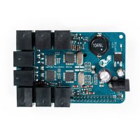
BrickPi+ Base Kit
BrickPi is best for someone who already has LEGO MINDSTORMS sensors and motors. The BrickPi connects..
रo 17,563.00
EV3 Infrared Beacon
This has been designed for use with the EV3 Infrared Seeker Sensor. The beacon emits an infrared sig..
रo 4,425.00
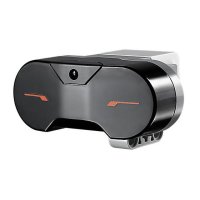
EV3 Infrared Sensor
The digital EV3 Infrared Seeking Sensor detects proximity to the robot and reads signals emitted by ..
रo 4,425.00
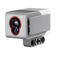
EV3 Color Sensor
The digital EV3 Color Sensor distinguishes between eight different colors. It also serves as a light..
रo 5,175.00 रo 5,885.00
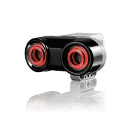
EV3 Ultrasonic Sensor
The digital EV3 Ultrasonic Sensor generates sound waves and reads their echoes to detect and measure..
रo 4,425.00
EV3 Gyro Sensor
The digital EV3 Gyro Sensor measures the robot’s rotational motion and changes in its orientation. S..
रo 4,425.00
Lego Mindstorms NXT Magnetic Sensor
The NXT Magnetic Sensor will enable you to build robots that can detect magnetic fields. The sensor ..
रo 2,865.00
Lego Mindstorms NXT EOPD
Accurately detect objects and small changes in distance to a target with the HiTechnic EOPD. The EOP..
रo 6,920.00
Lego Mindstorms NXT Angle Sensor
Measure axle rotation position and rotation speed with the HiTechnic Angle Sensor. The Angle Sensor ..
रo 6,920.00
Lego Mindstorms NXT Force Sensor
The NXT Force Sensor will enable you to build robots that can measure a physical force applied throu..
रo 5,000.00
Lego Mindstorms NXT Barometric Sensor
The NXT Barometric Sensor can be used as part of a weather station or to monitor altitude. The senso..
रo 6,920.00
HiTechnic NXT Extended Connector Cable
Extend your Mindstorms NXT robotic designs with the HiTechnic Extended Connector Cable . Build creat..
रo 100.00
HiTechnic NXT Touch Sensor Multiplexer
HiTechnic NXT Touch Sensor Multiplexer for LEGO Mindstorms NXT Introduction The NXT Touc..
रo 3,610.00
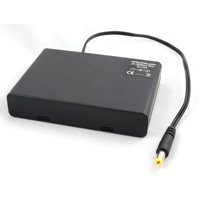
HiTechnic 9V-6xAA Battery Box
This Battery Box can be used to power the 360 IR Beacon replacing the beacon's optional 9v internal ..
रo 645.00
HiTechnic NXT SuperPro Prototype Board
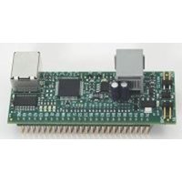
HiTechnic SuperPro Sensor for LEGO Mindstorms NXT Introduction The HiTechnic SuperPro Sensor..
रo 3,400.00

