


This compact breakout board makes it easy to use Allegro’s A4990 dual motor driver, which can control two bidirectional DC motors over a wide operating voltage range of 6 V to 32 V. It is capable of delivering a continuous 0.7 A to each motor channel, and onboard sense resistors enable the A4990 to limit the peak motor current to about 0.9 A per channel. The driver also features protection against reverse-voltage, under-voltage, over-voltage, over-current, and over-temperature.
Allegro’s A4990 is a dual H-bridge motor driver IC that can be used for bidirectional control of two brushed DC motors at 6 V to 32 V. It can supply up to 0.7 A continuously to each motor channel, and the current control feature of the A4990 limits the peak motor current to about 0.9 A per channel with the onboard sense resistors, making this a good choice for small, low-current motors that run on relatively high voltages. Since this board is a carrier for the A4990, we recommend careful reading of the A4990 datasheet (301k pdf). The board ships populated with all of its SMD components, including the A4990 and an additional FET for reverse battery protection.
For a single-channel driver with a DIR/PWM interface and a similar operating voltage range, please consider our DRV8801 carrier. For lower-voltage alternatives to the A4990, consider our DRV8833 andDRV8835 dual motor driver carriers.
We also carry an A4990 dual motor driver Arduino shield that makes it easy to incorporate this great driver into an Arduino project.
Features
- Dual-H-bridge motor driver: can drive two DC motors or one bipolar stepper motor
- Operating voltage: 6 V to 32 V1
- Output current: 0.7 A continuous per motor
- Current control limits peak current to 0.9 A per motor
- Inputs are 3V- and 5V-compatible
-
Robust:
- Reverse-voltage protection circuit
- Can survive input voltages up to 40 V2
- Under-voltage and over-voltage protection
- Over-temperature protection
- Short-to-supply, short-to-ground, and shorted-load protection on the motor outputs
1 Over-voltage protection typically kicks in at 34 V, but it can trigger at voltages as low as 32 V.
2 While the A4990 can tolerate input voltages as high as 50 V, the reverse-voltage protection MOSFET is only rated for 40 V.
Using the motor driver
 |
|
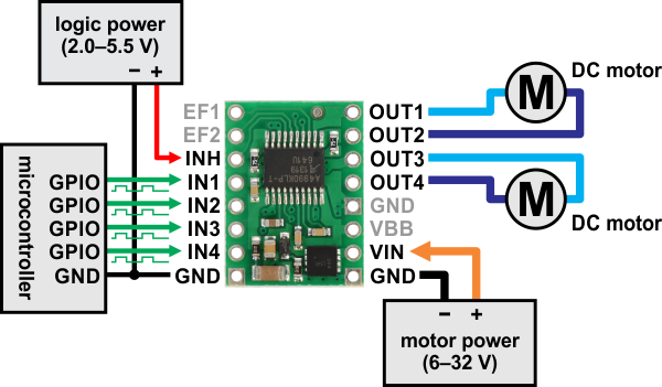
Minimal wiring diagram for connecting a microcontroller to an A4990 dual motor driver carrier. |
|---|
In a typical application, power connections are made on one side of the board and control connections are made on the other. The INH (inhibit) pin is pulled low internally, disabling the A4990 by default, and must be driven high (2.0–5.5 V) in order to enable the driver.
The OUT1 and OUT2 pins form one motor channel while the OUT3 and OUT4 pins form the other. The state of each output is controlled by a corresponding input (IN1 through IN4); note that IN2 and IN4 are inverted inputs. All four INx pins are pulled to their inactive states by default. See the truth tables in the A4990 datasheet for more information on how the inputs affect the driver outputs.
The EF1 and EF2 pins are open-drain outputs that are driven low by the chip to indicate active faults (the datasheet describes what each combination of EF1 and EF2 means). Otherwise, these pins remain in a floating state, so you will need to connect external pull-up resistors (or use microcontroller inputs with their built-in pull-ups enabled) if you want to monitor fault conditions on the driver.
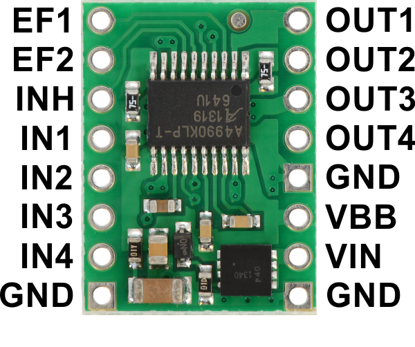
Pinout
 |
| PIN | Default State | Description |
|---|---|---|
| VIN | Reverse-protected 6 V to 32 V motor power supply connection. | |
| VBB | This pin gives access to the motor power supply after the reverse-voltage protection MOSFET (see the board schematic below). It can be used to supply reverse-protected power to other components in the system. It is generally intended as an output, but it can also be used to supply board power. | |
| GND | Ground connection points for the motor and logic power supplies. The control source and the motor driver must share a common ground. | |
| OUT1 | Motor A output +. | |
| OUT2 | Motor A output −. | |
| OUT3 | Motor B output +. | |
| OUT4 | Motor B output −. | |
| IN1 | LOW | Control input for OUT1. PWM can be applied to this pin. |
| IN2 | HIGH | Inverted control input for OUT2. PWM can be applied to this pin. |
| IN3 | LOW | Control input for OUT3. PWM can be applied to this pin. |
| IN4 | HIGH | Inverted control input for OUT4. PWM can be applied to this pin. |
| INH | LOW | Logic input that puts the A4990 into a low-power sleep mode when low. |
| EF1 | floating | Error flag output 1: driven low to indicate active fault status; floating otherwise. |
| EF2 | floating | Error flag output 2: driven low to indicate active fault status; floating otherwise. |
Current limiting
The A4990 can actively limit the current through the motors by using a fixed-frequency PWM current regulation (current chopping). This carrier board connects 0.075 Ω resistors to the current sense pins, which sets the current limit to a nominal 1 A per channel. In our tests, the board actually limited the motor current to slightly above 0.9 A.
Real-world power dissipation considerations
Even though the driver limits the motor current to about 0.9 A per channel, the chip by itself will overheat at lower currents. For example, in our tests at room temperature with no forced air flow, the chip was able to deliver 0.9 A per channel for approximately 20 s before the chip’s thermal protection kicked in. A continuous current of 0.7 A per channel was sustainable for many minutes without triggering a thermal shutdown. The actual current you can deliver will depend on how well you can keep the motor driver cool. The carrier’s printed circuit board is designed to draw heat out of the motor driver chip, but performance can be improved by adding a heat sink. Our tests were conducted at 100% duty cycle; PWMing the inputs will introduce additional heating proportional to the frequency (unless the A4990 is already PWMing the outputs to limit the current).
This product can get hot enough to burn you long before the chip overheats. Take care when handling this product and other components connected to it.
Included hardware
|
|
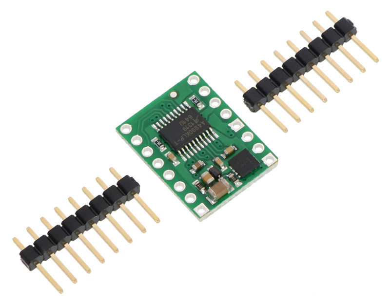
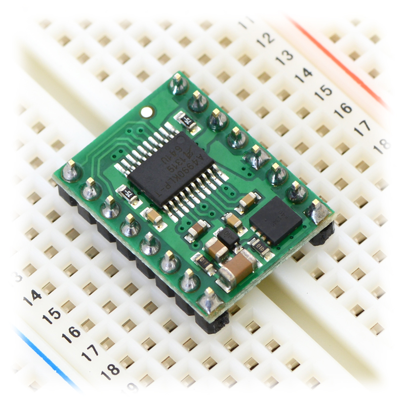
Two 1×8-pin breakaway 0.1″ male headers are included with the A4990 motor driver carrier, which can be soldered in to use the driver with perfboards, breadboards, or 0.1″ female connectors. (The headers might ship as a single 1×16 piece that can be broken in half.) When used with these header pins, the board can be oriented with the parts visible, as shown in the right picture above, or with the silkscreen visible, by soldering the headers in from the opposite side. You can also solder your motor leads and other connections directly to the board.
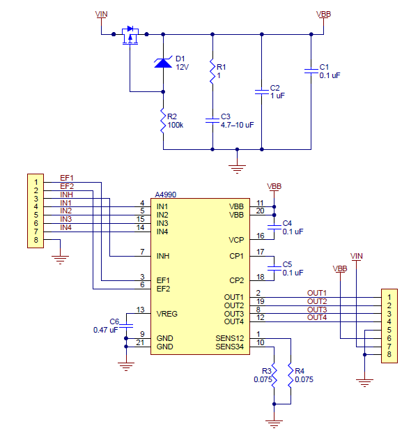
Schematic
 |
|
A4990 Dual Motor Driver Carrier schematic diagram. |
|---|
This schematic is also available as a downloadable pdf (118k pdf).
This compact breakout board makes it easy to use Allegro’s A4990 dual motor driver, which can control two bidirectional DC motors over a wide operating voltage range of 6 V to 32 V. It is capable of delivering a continuous 0.7 A to each motor channel, and onboard sense resistors enable the A4990 to limit the peak motor current to about 0.9 A per channel. The driver also features protection against reverse-voltage, under-voltage, over-voltage, over-current, and over-temperature.
Allegro’s A4990 is a dual H-bridge motor driver IC that can be used for bidirectional control of two brushed DC motors at 6 V to 32 V. It can supply up to 0.7 A continuously to each motor channel, and the current control feature of the A4990 limits the peak motor current to about 0.9 A per channel with the onboard sense resistors, making this a good choice for small, low-current motors that run on relatively high voltages. Since this board is a carrier for the A4990, we recommend careful reading of the A4990 datasheet (301k pdf). The board ships populated with all of its SMD components, including the A4990 and an additional FET for reverse battery protection.
For a single-channel driver with a DIR/PWM interface and a similar operating voltage range, please consider our DRV8801 carrier. For lower-voltage alternatives to the A4990, consider our DRV8833 andDRV8835 dual motor driver carriers.
We also carry an A4990 dual motor driver Arduino shield that makes it easy to incorporate this great driver into an Arduino project.
Features
- Dual-H-bridge motor driver: can drive two DC motors or one bipolar stepper motor
- Operating voltage: 6 V to 32 V1
- Output current: 0.7 A continuous per motor
- Current control limits peak current to 0.9 A per motor
- Inputs are 3V- and 5V-compatible
-
Robust:
- Reverse-voltage protection circuit
- Can survive input voltages up to 40 V2
- Under-voltage and over-voltage protection
- Over-temperature protection
- Short-to-supply, short-to-ground, and shorted-load protection on the motor outputs
1 Over-voltage protection typically kicks in at 34 V, but it can trigger at voltages as low as 32 V.
2 While the A4990 can tolerate input voltages as high as 50 V, the reverse-voltage protection MOSFET is only rated for 40 V.
Using the motor driver
|
|
|
Minimal wiring diagram for connecting a microcontroller to an A4990 dual motor driver carrier. |
|---|
In a typical application, power connections are made on one side of the board and control connections are made on the other. The INH (inhibit) pin is pulled low internally, disabling the A4990 by default, and must be driven high (2.0–5.5 V) in order to enable the driver.
The OUT1 and OUT2 pins form one motor channel while the OUT3 and OUT4 pins form the other. The state of each output is controlled by a corresponding input (IN1 through IN4); note that IN2 and IN4 are inverted inputs. All four INx pins are pulled to their inactive states by default. See the truth tables in the A4990 datasheet for more information on how the inputs affect the driver outputs.
The EF1 and EF2 pins are open-drain outputs that are driven low by the chip to indicate active faults (the datasheet describes what each combination of EF1 and EF2 means). Otherwise, these pins remain in a floating state, so you will need to connect external pull-up resistors (or use microcontroller inputs with their built-in pull-ups enabled) if you want to monitor fault conditions on the driver.
Pinout
|
|
| PIN | Default State | Description |
|---|---|---|
| VIN | Reverse-protected 6 V to 32 V motor power supply connection. | |
| VBB | This pin gives access to the motor power supply after the reverse-voltage protection MOSFET (see the board schematic below). It can be used to supply reverse-protected power to other components in the system. It is generally intended as an output, but it can also be used to supply board power. | |
| GND | Ground connection points for the motor and logic power supplies. The control source and the motor driver must share a common ground. | |
| OUT1 | Motor A output +. | |
| OUT2 | Motor A output −. | |
| OUT3 | Motor B output +. | |
| OUT4 | Motor B output −. | |
| IN1 | LOW | Control input for OUT1. PWM can be applied to this pin. |
| IN2 | HIGH | Inverted control input for OUT2. PWM can be applied to this pin. |
| IN3 | LOW | Control input for OUT3. PWM can be applied to this pin. |
| IN4 | HIGH | Inverted control input for OUT4. PWM can be applied to this pin. |
| INH | LOW | Logic input that puts the A4990 into a low-power sleep mode when low. |
| EF1 | floating | Error flag output 1: driven low to indicate active fault status; floating otherwise. |
| EF2 | floating | Error flag output 2: driven low to indicate active fault status; floating otherwise. |
Current limiting
The A4990 can actively limit the current through the motors by using a fixed-frequency PWM current regulation (current chopping). This carrier board connects 0.075 Ω resistors to the current sense pins, which sets the current limit to a nominal 1 A per channel. In our tests, the board actually limited the motor current to slightly above 0.9 A.
Real-world power dissipation considerations
Even though the driver limits the motor current to about 0.9 A per channel, the chip by itself will overheat at lower currents. For example, in our tests at room temperature with no forced air flow, the chip was able to deliver 0.9 A per channel for approximately 20 s before the chip’s thermal protection kicked in. A continuous current of 0.7 A per channel was sustainable for many minutes without triggering a thermal shutdown. The actual current you can deliver will depend on how well you can keep the motor driver cool. The carrier’s printed circuit board is designed to draw heat out of the motor driver chip, but performance can be improved by adding a heat sink. Our tests were conducted at 100% duty cycle; PWMing the inputs will introduce additional heating proportional to the frequency (unless the A4990 is already PWMing the outputs to limit the current).
This product can get hot enough to burn you long before the chip overheats. Take care when handling this product and other components connected to it.
Included hardware
|
|
Two 1×8-pin breakaway 0.1″ male headers are included with the A4990 motor driver carrier, which can be soldered in to use the driver with perfboards,
| Electrical Specifications | |
| Output Current | 0.7A |
| Minimum Operating Voltage | 6V |
| Maximum Operating Voltage | 32V |
| Physical Attributes | |
| Weight | 0.8g |
| Dimensions | 0.6″ × 0.8″ |
| Additional Information | |
| Warranty | |
Pololu 2137 A4990 Dual Motor Driver Carrier
- Brand: Pololu
- Product Code: Pololu-Dual-Motor-Driver-A4990
- Reward Points: 6
- Availability: In Stock
- रo 633.00
-
रo 608.00
- Price in reward points: 633
-
- 22 or more रo 628.00
- 45 or more रo 623.00
- 112 or more रo 618.00
- 225 or more रo 613.00
Related Products

L298N Motor Driver Board
The L298N driver module, using ST' L298N chip, can directly drive two 3-30V DC motor, and provide a ..
रo 195.00

L298P 2A Motor Shield For Arduino
This DFRobot Arduino Compatible Motor Shield (2A) uses L298P chip which allow to drive two 7-12V DC..
रo 1,183.00 रo 1,364.00

L298N - Dual Full Bridge Driver
The L298N is a high voltage, high current, dual full bridge driver designed to accept standard TTL l..
रo 150.00

L298 Dual H-Bridge Motor Driver
Double H driver module uses ST L298N dual full-bridge driver, an integrated monolithic circuit in a ..
रo 2,519.00

Stepper Motor Driver A4988
A4988 is a complete microstepping motor driver with built-in translator for easy operation. This pro..
रo 140.00

Pololu 3764/3765 DRV8434A Stepper Motor Driver Carrier
This breakout board for TI’s DRV8434A microstepping bipolar stepper motor driver offers microsteppin..
रo 1,057.00 रo 1,101.00

1A Motor Shield for Arduino
1A Motor Shield for Arduino This Motor shield for Arduino uses L293 chip which allow to dri..
रo 1,502.00 रo 1,730.00

Stepper Motor Driver - Easy Driver A3967
Each Easy Driver can drive up to about 750mA per phase of a bi-polar stepper motor. It defaults to 8..
रo 210.00

Pololu 2134 / 2874 DRV8834 Low-Voltage Stepper Motor Driver Carrier
This is a breakout board for TI’s DRV8834 microstepping bipolar stepper motor driver. It has a pinou..
रo 602.00 रo 628.00

Pololu 2971 DRV8880 Stepper Motor Driver Carrier
This breakout board for TI’s DRV8880 microstepping bipolar stepper motor driver features adjustable ..
रo 917.00 रo 955.00

Pololu Dual 2755/2756 MC33926 Motor Driver for Raspberry Pi
This add-on board enables a Raspberry Pi B+, A+, Pi 2, or Pi 3 to drive a pair of bru..
रo 2,802.00 रo 2,919.00

Pololu 1213 Dual MC33926 Motor Driver Carrier
This dual brushed DC motor driver, based on Freescale’s MC33926 full H-bridge, has a wide operating ..
रo 2,802.00 रo 2,919.00

Pololu 1212 MC33926 Motor Driver Carrier
This breakout board for Freescale’s MC33926 full H-bridge has an operating range of 5 – 28 V and can..
रo 1,512.00 रo 1,575.00

Pololu 2130 DRV8833 Dual Motor Driver Carrier
This tiny breakout board for TI’s DRV8833 dual motor driver can deliver 1.2 A per channel continuous..
रo 754.00 रo 786.00

Pololu 2135 DRV8835 Dual Motor Driver Carrier
This tiny breakout board for TI’s DRV8835 dual motor driver can deliver 1.2 A per channel conti..
रo 376.00 रo 391.00

Pololu 2990 DRV8838 Single Brushed DC Motor Driver Carrier
This tiny breakout board for TI’s DRV8838 motor driver can deliver a continuous 1.7 A (1.8 A peak) t..
रo 340.00 रo 354.00

Pololu 2961 MAX14870 Single Brushed DC Motor Driver Carrier
This compact breakout board for Maxim’s MAX14870 motor driver offers a wide operating voltage range ..
रo 754.00 रo 786.00

Pololu 2960 BD65496MUV Single Brushed DC Motor Driver Carrier
This compact breakout board for ROHM’s BD65496MUV motor driver offers an operating voltage range of ..
रo 1,071.00 रo 1,275.00

Pololu 2136 DRV8801 Single Brushed DC Motor Driver Carrier
This tiny breakout board for TI’s DRV8801 provides a modern alternative to classic motor drivers suc..
रo 1,044.00 रo 1,087.00

Pololu 1112 Qik 2s12v10 Dual Serial Motor Controller
This powerful motor controller allows variable speed and direction control of two large, brushed DC ..
रo 14,110.00

Pololu 1110 Qik 2s9v1 Dual Serial Motor Controller
This small, inexpensive motor controller allows variable speed and direction control of two small, b..
रo 3,551.00

L298 Dual H-Bridge Motor Driver Module
New L298 Dual H-Bridge Motor Driver Features: Working mode: H bridge ..
रo 235.00

ULN2003 Stepper Motor Driver Board
ULN2003 Stepper Motor Driver Board A B C D four-phase LED indicates the status of the ..
रo 74.00

Pololu 2968 / 2969 Stepper Motor Driver Carrier, Digital Current Control MP6500
This product is a carrier board or breakout board for the MP6500 stepper motor driver from Monolithi..
रo 520.00 रo 549.00

Pololu 2966 / 2967 Stepper Motor Driver Carrier, Potentiometer Current Control MP6500
This product is a carrier board or breakout board for the MP6500 stepper motor driver from Monolithi..
रo 527.00 रo 549.00

Pololu 707/708 VNH2SP30/VNH3SP30 Dual Motor Driver Carrier MD03A 708 707
The Pololu dual high-power motor drivers are compact carriers for the VNH3SP30 and VNH2SP30 motor dr..
रo 14,932.00 रo 17,634.00

Pololu 2878 / 2879 STSPIN820 Stepper Motor Driver Carrier
This breakout board for STMicro’s STSPIN820 microstepping bipolar stepper motor driver offers micros..
रo 1,532.00 रo 1,595.00

Pololu 3098 / 3099 Stepper Motor Driver Compact Carrier TB67S279FTG
This breakout board for Toshiba’s TB67S279FTG microstepping bipoloar stepper motor driver is arrange..
रo 816.00 रo 850.00

Pololu 3096 / 3097 Stepper Motor Driver Compact Carrier TB67S249FTG
This breakout board for Toshiba’s TB67S249FTG microstepping bipoloar stepper motor driver is arrange..
रo 982.00 रo 1,023.00

Pololu 5047/5046/5045 Motoron M2S24v16 Dual High-Power Motor Controller Shield for Arduino
The Motoron M2S24v16 Dual High-Power Motor Controller Shield for Arduino makes it easy to control tw..
रo 7,681.00 रo 8,001.00
